关于上采样和下采样的理论整理。
上采样和下采样
1 上采样
放大图像(上采样(upsampling)或图像插值(interpolating))的主要目的是放大原图像,从而可以显示在更高分辨率的显示设备上。对图像的缩放操作并不能带来更多关于该图像的信息,因此图像的质量将不可避免地受到影响。然而,有的缩放方法能够增加图像的信息,从而使得缩放后的图像质量超过原图质量。
1.1 线性插值
1.1.1 最近邻插值算法
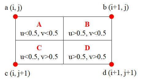
当图片放大时,缺少的像素通过直接使用与之最近原有颜色生成,在待求像素的四邻像素中,将距离待求像素最近的邻灰度赋给待求像素。设待求像素的坐标为 (i+u,j+v),i,j 为正整数,u,v 为大于 0 小于 1 的小数,则待求像素灰度的值 f(i+u,j+v) 的计算方式如下图所示:

图-1 最近邻插值
如果 (i+u,j+v) 落在 A 区域内,即 u<0.5,v<0.5,则将 a 点的像素值赋给待求像素,其他三种情况同理。最邻近法计算量较小,但可能会造成插值生成的图像灰度上的不连续,在灰度变化的地方可能出现明显的锯齿状。
1.1.2 双线性插值算法
核心思想是在两个方向分别进行一次线性插值。
-
先确定变量
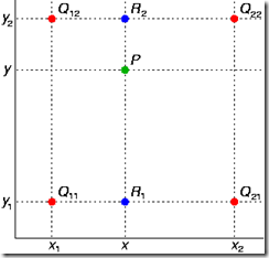
- 四个像素点:Q11,Q12,Q21,Q22
- 像素点坐标:(x1,y1),(x1,y2),(x2,y1),(x2,y2)
- 像素值:f(Q11),f(Q12),f(Q21),f(Q22)
- 横向插值插入的两个点为 R1,R2,坐标为 (x,y1),(x,y2)
- 纵向插值插入的一个点为 P,坐标为 (x,y)

图-2 双线性插值
-
插值的目的
图像扩展,由已知的像素点的值来计算出来原本不存在的像素点。
-
插值的方法
-
计算过程
-
计算横向插值,由 Q22 和 Q12 计算 R2 的过程:
x2−x1f(Q22)−f(Q12)≈x2−xf(Q22)−f(R2)
交叉相乘并化简,得到:
f(R2)≈x2−x1x2−xf(Q12)+x2−x1x−x1f(Q22)
-
同理,由 Q11 和 Q21 计算 R1:
f(R1)≈x2−x1x2−xf(Q11)+x2−x1x−x1f(Q21)
-
结合 R1 和 R2 在 y 方向插值得到 P:
y2−y1f(R2)−f(R1)≈y2−yf(R2)−f(P)
化简得:
f(P)≈y2−y1y2−yf(R1)+y2−y1y−y1f(R2)
将 f(R1) 和 f(R2) 带入 f(P) 得到:
f(P)≈(x2−x1)(y2−y1)f(Q11)(x2−x)(y2−y)+(x2−x1)(y2−y1)f(Q21)(x−x1)(y2−y)+(x2−x1)(y2−y1)f(Q12)(x2−x)(y−y1)+(x2−x1)(y2−y1)f(Q22)(x−x1)(y−y1)
1.1.3 双三次插值算法
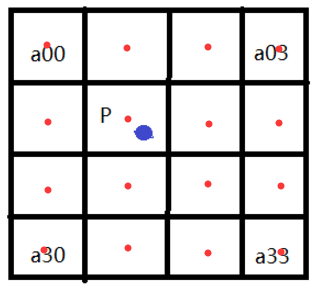
双三次插值算法计算复杂、速度较慢。其并不是通过线性插值,而是通过邻近的 4×4 (=16) 个像素做加权。假设原图 A 大小为 m×n,缩放 K 倍后图 B 大小为 M×N,即 K=M/m。A 中每个像素点都是已知的,要求出 B 中像素点 B(X,Y) 的值,需先找到 B(X,Y) 在 A 中对应的像素 A(x,y),再根据源图像 A 距离像素 A(x,y) 最近的 16 个像素点作为计算 A(X,Y) 的参数,利用 BiCubic 基函数求出 16 个像素点的权重,再做加权叠加得到 B(X,Y) 的值。
根据比例关系 x/X=m/M=1/K,可以得到 B(X,Y) 在 A 中的对应坐标:
A(x,y)=A(X⋅Mm,Y⋅Nn)=A(KX,KY)

图-3 双三次插值
由于计算出的 A(x,y) 中会出现小数部分,假设 B(X,Y) 在 A 中的对应点记为 P(即前面的 A(x,y)),则将 P 的坐标记为 P=(x+u,y+v),注意其中 x,y 表示整数部分(蓝点格中红点的像素坐标),u,v 表示小数部分(蓝点到蓝点格中红点的距离)。由此可以得到 P 附近的 16 个像素,将这些像素记为 aij (i,j=0,1,2,3)。
构造 BiCubic 函数:
W(x)=
\begin{cases}
(a+2) \abs{x}^3 + (a+3) \abs{x}^2 + 1,\ &\mathrm{for}\ \abs{x}\le1 \\
a \abs{x}^3 - 5a\abs{x}^2 + 8a\abs{x} - 4a, &\mathrm{for}\ 1<\abs{x}<2 \\ 0, &\mathrm{otherwise} \end{cases}\\ 其中\ a\ 为超参数\mathrm{(可取\ 0.5)}
BiCubic 基函数是一维的,而像素坐标是二维的,因此将像素点的行与列分开计算:BiCubic 中参数 x 表示像素点到 P 的距离,例如 a00 到 P 的距离为 (1+u,1+v),因此 a00 横坐标的权重为 row0=W(1+u),纵坐标的权重为 col0=W(1+v),a00 对 B(X,Y) 的贡献为 a00×row0×col0。从而,B(X,Y) 的像素值为:
B(X,Y)=i=0∑3j=0∑3aij×rowi×coljrow0=W(1+u), row1=W(u), row2=W(1−u), row3=W(2−u)col0=W(1+v), col1=W(v), col2=W(1−v), col3=W(2−v)
C++ 代码:
1
2
3
4
5
6
7
8
9
10
11
12
13
14
15
16
17
18
19
20
21
22
23
24
25
26
27
28
29
30
31
32
33
34
35
36
37
38
39
40
41
42
43
44
45
46
47
48
49
50
51
52
53
54
55
56
57
58
59
60
61
62
63
64
65
66
67
68
69
70
71
72
73
74
75
76
77
78
79
80
81
82
83
84
85
86
87
88
89
90
91
92
93
94
95
96
97
98
99
100
101
102
103
104
105
106
107
108
109
110
111
112
113
114
115
116
117
118
119
120
121
122
123
124
125
126
127
128
129
130
131
132
133
134
135
136
137
138
139
140
141
142
143
144
145
146
147
148
149
150
151
152
153
154
155
156
157
158
159
160
161
162
163
164
165
166
167
168
169
170
171
172
173
174
175
176
177
178
179
180
181
182
183
184
185
186
187
188
189
190
191
192
193
194
195
196
197
198
199
200
201
202
203
204
205
206
207
| #include "opencv2/imgproc/imgproc.hpp"
#include "opencv2/highgui/highgui.hpp"
#include <iostream>
#include <cmath>
#include <fstream>
using namespace cv;
using namespace std;
#define PI 3.14159265
float BiCubicPoly(float x);
void MyScaleBiCubicInter(Mat& src, Mat& dst, float TransMat[3][3]);
int main(int argc, char** argv) {
char* imageName = "images/Lenna_256.png";
Mat image;
image = imread(imageName,1);
if (!image.data) {
cout << "No image data" << endl;
return -1;
}
namedWindow("image", CV_WINDOW_AUTOSIZE);
imshow("image", image);
Mat dst;
float transMat[3][3] = {{2.0, 0, 0}, {0, 2.0, 0}, {0, 0, 1}};
MyScaleBiCubicInter(image, dst, transMat);
namedWindow("out_image", CV_WINDOW_AUTOSIZE);
imshow("out_image", dst);
imwrite("Lenna_scale_biCubic2.jpg", dst);
waitKey(0);
return 0;
}
float BiCubicPoly(float x) {
float abs_x = abs(x);
float a = -0.5;
if ( abs_x <= 1.0 ) {
return (a+2)*pow(abs_x,3) - (a+3)*pow(abs_x,2) + 1;
} else if( abs_x < 2.0 ) {
return a*pow(abs_x,3) - 5*a*pow(abs_x,2) + 8*a*abs_x - 4*a;
}
else
return 0.0;
}
void MyScaleBiCubicInter(Mat& src, Mat& dst, float TransMat[3][3]) {
CV_Assert(src.data);
CV_Assert(src.depth() != sizeof(uchar));
float left = 0;
float right = 0;
float top = 0;
float down = 0;
float x = src.cols * 1.0f;
float y = 0.0f;
float u1 = x * TransMat[0][0] + y * TransMat[0][1];
float v1 = x * TransMat[1][0] + y * TransMat[1][1];
x = src.cols * 1.0f;
y = src.rows * 1.0f;
float u2 = x * TransMat[0][0] + y * TransMat[0][1];
float v2 = x * TransMat[1][0] + y * TransMat[1][1];
x = 0.0f;
y = src.rows * 1.0f;
float u3 = x * TransMat[0][0] + y * TransMat[0][1];
float v3 = x * TransMat[1][0] + y * TransMat[1][1];
left = min( min( min(0.0f,u1), u2 ), u3);
right = max( max( max(0.0f,u1), u2 ), u3);
top = min( min( min(0.0f,v1), v2 ), v3);
down = max( max( max(0.0f,v1), v2 ), v3);
dst.create(int(abs(right-left)), int(abs(down-top)), src.type());
CV_Assert(dst.channels() == src.channels());
int channels = dst.channels();
int i,j;
uchar* p;
uchar* q0;
uchar* q1;
uchar* q2;
uchar* q3;
for (i = 0; i < dst.rows; ++i) {
p = dst.ptr<uchar>(i);
for (j = 0; j < dst.cols; ++j) {
x = (j+left)/TransMat[0][0];
y = (i+top)/TransMat[1][1];
int x0 = int(x) - 1;
int y0 = int(y) - 1;
int x1 = int(x);
int y1 = int(y);
int x2 = int(x) + 1;
int y2 = int(y) + 1;
int x3 = int(x) + 2;
int y3 = int(y) + 2;
if ((x0 >= 0) && (x3 < src.cols) && (y0 >= 0) && (y3 < src.rows)) {
q0 = src.ptr<uchar>(y0);
q1 = src.ptr<uchar>(y1);
q2 = src.ptr<uchar>(y2);
q3 = src.ptr<uchar>(y3);
float dist_x0 = BiCubicPoly(x-x0);
float dist_x1 = BiCubicPoly(x-x1);
float dist_x2 = BiCubicPoly(x-x2);
float dist_x3 = BiCubicPoly(x-x3);
float dist_y0 = BiCubicPoly(y-y0);
float dist_y1 = BiCubicPoly(y-y1);
float dist_y2 = BiCubicPoly(y-y2);
float dist_y3 = BiCubicPoly(y-y3);
float dist_x0y0 = dist_x0 * dist_y0;
float dist_x0y1 = dist_x0 * dist_y1;
float dist_x0y2 = dist_x0 * dist_y2;
float dist_x0y3 = dist_x0 * dist_y3;
float dist_x1y0 = dist_x1 * dist_y0;
float dist_x1y1 = dist_x1 * dist_y1;
float dist_x1y2 = dist_x1 * dist_y2;
float dist_x1y3 = dist_x1 * dist_y3;
float dist_x2y0 = dist_x2 * dist_y0;
float dist_x2y1 = dist_x2 * dist_y1;
float dist_x2y2 = dist_x2 * dist_y2;
float dist_x2y3 = dist_x2 * dist_y3;
float dist_x3y0 = dist_x3 * dist_y0;
float dist_x3y1 = dist_x3 * dist_y1;
float dist_x3y2 = dist_x3 * dist_y2;
float dist_x3y3 = dist_x3 * dist_y3;
switch (channels) {
case 1:
{
break;
}
case 3:
{
p[3*j] = (uchar)(q0[3*x0] * dist_x0y0 +
q1[3*x0] * dist_x0y1 +
q2[3*x0] * dist_x0y2 +
q3[3*x0] * dist_x0y3 +
q0[3*x1] * dist_x1y0 +
q1[3*x1] * dist_x1y1 +
q2[3*x1] * dist_x1y2 +
q3[3*x1] * dist_x1y3 +
q0[3*x2] * dist_x2y0 +
q1[3*x2] * dist_x2y1 +
q2[3*x2] * dist_x2y2 +
q3[3*x2] * dist_x2y3 +
q0[3*x3] * dist_x3y0 +
q1[3*x3] * dist_x3y1 +
q2[3*x3] * dist_x3y2 +
q3[3*x3] * dist_x3y3 ) ;
p[3*j+1] = (uchar)(q0[3*x0+1] * dist_x0y0 +
q1[3*x0+1] * dist_x0y1 +
q2[3*x0+1] * dist_x0y2 +
q3[3*x0+1] * dist_x0y3 +
q0[3*x1+1] * dist_x1y0 +
q1[3*x1+1] * dist_x1y1 +
q2[3*x1+1] * dist_x1y2 +
q3[3*x1+1] * dist_x1y3 +
q0[3*x2+1] * dist_x2y0 +
q1[3*x2+1] * dist_x2y1 +
q2[3*x2+1] * dist_x2y2 +
q3[3*x2+1] * dist_x2y3 +
q0[3*x3+1] * dist_x3y0 +
q1[3*x3+1] * dist_x3y1 +
q2[3*x3+1] * dist_x3y2 +
q3[3*x3+1] * dist_x3y3 ) ;
p[3*j+2] = (uchar)(q0[3*x0+2] * dist_x0y0 +
q1[3*x0+2] * dist_x0y1 +
q2[3*x0+2] * dist_x0y2 +
q3[3*x0+2] * dist_x0y3 +
q0[3*x1+2] * dist_x1y0 +
q1[3*x1+2] * dist_x1y1 +
q2[3*x1+2] * dist_x1y2 +
q3[3*x1+2] * dist_x1y3 +
q0[3*x2+2] * dist_x2y0 +
q1[3*x2+2] * dist_x2y1 +
q2[3*x2+2] * dist_x2y2 +
q3[3*x2+2] * dist_x2y3 +
q0[3*x3+2] * dist_x3y0 +
q1[3*x3+2] * dist_x3y1 +
q2[3*x3+2] * dist_x3y2 +
q3[3*x3+2] * dist_x3y3 ) ;
float thre = 198.0f;
if ((abs(p[3*j]-q1[3*x1]) > thre) || (abs(p[3*j+1]-q1[3*x1+1]) > thre) ||
(abs(p[3*j+2]-q1[3*x1+2]) > thre)) {
p[3*j] = q1[3*x1];
p[3*j+1] = q1[3*x1+1];
p[3*j+2] = q1[3*x1+2];
}
break;
}
}
}
}
}
}
|
1.2 深度学习
1.2.1 转置卷积(反卷积)
1.2.1.1 正向卷积
假设输入图像 input 的尺寸为 4×4,元素矩阵为:
input=⎣⎢⎢⎡x1x5x9x13x2x6x10x14x3x7x11x15x4x8x12x16⎦⎥⎥⎤
卷积核 kernel 的尺寸为 3×3,元素矩阵为:
kernel=⎣⎡w0,0w1,0w2,0w0,1w1,1w2,1w0,2w1,2w2,2⎦⎤
设定步长 stride=1,填充 padding=0,即 i=4,k=3,s=1,p=0,按照卷积计算公式,根据 o=⌊si+2p−k⌋+1 得到输出图像尺寸为 2×2。
把 input 展开为一个列向量 X:
X=[x1x2x3x4x5x6x7x8x9x10x11x12x13x14x15x16]T
输出图像展开为列向量 Y:
Y=[y1y2y3y4]T
对于输入 X 和输出 Y,可以用矩阵运算描述为:
Y=CX
通过推导,可以得到稀疏矩阵 C:
C=⎣⎢⎢⎡w0,0000w0,1w0,000w0,2w0,1000w0,200w1,00w0,00w1,1w1,0w0,1w0,0w1,2w1,1w0,2w0,10w1,20w0,2w2,00w1,00w2,1w2,0w1,1w1,0w2,2w2,1w1,2w1,10w2,20w1,200w2,0000w2,1w2,000w2,2w2,1000w2,2⎦⎥⎥⎤
反卷积就是要对这个矩阵运算过程进行逆运算,通过 C 和 Y 求 X,通过各个矩阵的尺寸大小,可以得到逆运算过程为:
X=CTY
如果代入数字计算会发现,反卷积的操作只是恢复了矩阵 X 的尺寸大小,并不能恢复 X 的每个元素值,只能保证矩阵大小一致。
1.2.1.2 反卷积
记:
osipk=output size=stride=input size=padding=kernel size
卷积的尺寸关系为:
o=⌊si+2p−k⌋+1
反卷积的尺寸关系为:
-
若 (o+xp−k)mods=0:
o′=s(i′−1)+k−2p
-
否则:
o′=s(i′−1)+a+k−2p
实际上卷积和反卷积只是两个有关联的操作,但并不是互为逆运算,仅仅是在形状上存在互逆的关系。
1.2.1.3 反卷积的应用
在 ResNet、GoogleNet 中,最后一层卷积输出的若干特征图尺寸为 7×7,若想通过上采样还原为原始图像的 224×224,则带入公式:
o=s(i−1)+k−2p, where o=224,i=7
此处取 (o+2p−k)mods=0,因此可得:
6s+k−2p=0
经过实验,可以得到合适的一组取值:
s=32, p=16, k=64
1.2.2 其他基于深度学习的算法
- PixelShuffle
- DUpsampling
- Meta-Upscale
- CAPAFE
1.3 其他上采样算法
- Inverse Distance to a Power(反距离加权插值法)
- Kriging(克里金插值法)
- Minimum Curvature(最小曲率)
- Modified Shepard’s Method(改进谢别德法)
- Natural Neighbor(自然邻点插值法)
- Polynomial Regression(多元回归法)
- Radial Basis Function(径向基函数法)
- Triangulation with Linear Interpolation(线性插值三角网法)
- Moving Average(移动平均法)
- Local Polynomial(局部多项式法)
2 下采样
缩小图像(下采样(subsampled)或降采样(downsampled))的主要目的为:
- 使得图像符合显示区域的大小
- 生成对应图像的缩略图
2.1 下采样的实现
-
方法一:for 循环隔行隔列循环遍历每一个像素点
1
2
3
4
5
6
7
8
9
10
11
12
13
14
15
16
17
18
19
20
21
22
23
|
clear all;
close all;
clc;
img = imread('...');
n = 2;
img = rgb2gray(img);
[h w] = size(img);
L = 1;
R = 1;
img_down = zeros(256,256);
for j = 1:n:h
for i = 1:n:w
img_down(L, R) = img(j, i);
R = R+1;
end
L = L+1;
R = 1;
end
|
-
方法二:矩阵隔行隔列赋值
1
2
3
|
img_down = img(1:n:512, 1:n:512);
imshowpair(img,(uint8(img_down)), 'montage');
|
方法二比方法一在计算上会有更高的效率。
2.2 DCT 域采样算法
1
2
3
4
5
6
7
8
9
10
11
12
13
14
15
16
17
18
19
20
21
22
23
24
25
26
27
28
29
30
31
32
33
|
I = imread('...');
I = rgb2gray(I);
figure(1);
imshow(I);
[width, height] = size(I);
block_size_x = 8;
block_size_y = 8;
x_block_num = width / block_size_x;
y_block_num = height / block_size_y;
z_dst = zeros(width / 2,height / 2);
pfun1 = @dct2;
I_freq = blkproc(I, [8 8], pfun1);
for i = 1: x_block_num
for j = 1 : y_block_num
P = I_freq((i-1) * 8 + 1: (i-1) * 8 + 4, (j-1) * 8 + 1: (j-1) * 8 + 4);
P = P/2.0;
z_dst((i-1) * 4 + 1: (i-1) * 4 + 4, (j-1) * 4 + 1: (j-1) * 4 + 4) = P;
end
end
pfun2 = @idct2;
J = blkproc(z_dst, [4 4], pfun2);
J = uint8(round(J));
figure(2);
imshow(J);
|
参考

 图-2 双线性插值